

February 2016 Newsletter
Newsletters Posted on Mon, February 08, 2016 21:28:15- Comments(0) https://news.firebirds.org.uk/?p=84
January 2016 Newsletter
Newsletters Posted on Sun, February 07, 2016 20:52:07- Comments(0) https://news.firebirds.org.uk/?p=83
December 2015 Newsletter
Newsletters Posted on Sun, February 07, 2016 20:51:12- Comments(0) https://news.firebirds.org.uk/?p=82
November 2015 Newsletter
Newsletters Posted on Tue, November 10, 2015 21:26:11- Comments(0) https://news.firebirds.org.uk/?p=81
October 2015 Newsletter
Newsletters Posted on Tue, November 10, 2015 21:25:22- Comments(0) https://news.firebirds.org.uk/?p=80
Quads FPV and Airworthyness
Safety Matters Posted on Sun, September 13, 2015 09:58:50Thank you to Geoff our safety officer for the following safety notices.
Just a couple of reminders this month.
1) FPV, Quads and aerial photography: Firstly, and most importantly, if you fly FPV it is MANDATORY that you enlist the help of another to act as watchman. Apart from being a legal requirement it makes good sense.
There are no specific club rules about where to fly quads, but please bear in mind a) that something small buzzing around relatively close in can be very distracting to other pilots and b) If others are in the air, hovering is not allowed over the strip unless all other pilots are ok about it. Ask first. If you wish to hover in order to get footage of models flying please do it at some distance and well away from the take-off, landing and flightpath of the other models. Bear in mind too that there are national regulations in place in respect or aerial photography. Please make sure you are aware of them. (I’m sure John Hoddinott will be able to point you in the right direction if you ask him nicely). There is some fantastic footage around taken from these machines and they are great fun, so we really don’t want to discourage or restrict their use unless absolutely necessary. Just be sensible, and try not to get in the way of fixed wing flyers.
2) The second reminder is that whatever you put in the air, it is your responsibility to ensure that it is airworthy. This is particularly pertinent with the ready built models that most of us fly nowadays. First thing I always check is the engine mount and wing fixing plates. Do they look up to the job? A bit of re-enforcing with epoxy or fibre glass is often appropriate. While we are at it, what about the servo mounts? Are these properly fixed? In 50 flights time the fuselage around the engine and in the tank bay will often become fuel soaked, so give it all a coat of proofer before you start assembly. How about the undercarriage mounting? It is much easier (and lighter!) to add some subtle re-enforcing now, before it breaks! If the control surfaces are already hinged, give them a good tug, and re-glue the hinges if necessary. If the canopy or cowl/battery hatch is removable, are you happy that the method of retaining them is ok? Again, much easier to do something about it now. Lastly, have a good look at the control horns, clevises and push rods; if in any doubt, change them. Things are a lot better now, but it has been known for Chinese manufacturers to alter the original plastic specification if they can find something cheaper!
That’s about it. If you take care at the building stage, the model will last a lot longer, be safer AND stay in one piece. Happy Flying!
- Comments(0) https://news.firebirds.org.uk/?p=79
Failsafes Batteries and No Fly Zones
Safety Matters Posted on Sun, September 13, 2015 09:56:34Many thanks to Geoff our resident safety officer for supplying the following article.
Well finally the good weather seems to be here for a bit, and with it hopefully somewhat more of us at the strip, so this month just a few reminders.
1 FAILSAFES Please remember that setting the failsafe on your radio (if it has this facility & most now do) is not only advisable, it is a legal requirement. If you switch off your transmitter the minimum requirement is that the throttle goes to low. Check this at the beginning of each session. Not having this facility enabled can affect your insurance in the event of an accident. The situation with helis is a bit vague – check the BMFA website for guidance.
2 BATTERIES I find that after a year, the performance of NiMH cells drops off considerably. The first sign is that they appear to be charged quicker than normal (If you are using a fast charger). A lot of chargers are capable of cycling the battery and then giving a readout of capacity. If you can do this you will probably be shocked at how bad some batteries that are a few years old have become! Don’t risk it – change the flight pack!
Most electric set-ups include a BEC (Battery Eliminator Circuit) so the Receiver and Servos all work off the LiPo powering the motor. If that fails completely you are really stuffed as you won’t have any control at all! Anything larger than a foamy park flyer really ought to have a separate flight pack for the Receiver and servos so if the worst ever happened you’ll still be able to land under control. Fitting a separate battery means you need to cut the red wire from the speed controller; if you are not sure about this, ask someone!
3 NO FLY AREAS I recently had a rather embarrassing crash due to dis-orientation. In mitigation all I can say is that it was an autogyro, so a bit of a strange shape, but nevertheless I really should have been more careful! Now what surprised me was that I thought it came down relatively close in the next field over by the Scouts, but I was a bit horrified to find it no more than 25 metres from the boundary, and I guess 100 metres from their actual field! The moral is, distances can be deceptive in the air! Keep well clear of the Scouts’ field.
- Comments(0) https://news.firebirds.org.uk/?p=78
September 2015
Down at the field Posted on Sun, September 13, 2015 08:55:55Well, there have been some good flying days over the past month with quite a lot of really rubbish ones too. Many thanks to Paul and Rob who supplied me with some great pictures.
Here’s a picture from one day that turned out beautifully calm and sunny but started with a bit of rain, hence the cover over my plane in the foreground and Pete scanning the skies for any further signs of precipitation.

Paul was working out the niggles with his recently acquired Ultimate Bipe.
Although the power was adequate, it wasn’t quite up to Paul standards. So maybe we’ll see some changes up front.

Here she is flying and you’ll notice that this shot is from above. It is a movie-still taken by one of Rob’s planes.
 Rob managed to catch quite a few fleeting moments of other aircraft passing through his camera’s field of view.
…And here is Rob getting ready to start his WOT4, which he can usually manage with a quick back-flip of the spinner. This is a trick I first saw Russell do with one of my planes.

Alan just getting his Majestic Major ready for lift off. This is a lovely thing to fly and we had some great goes with it.

Sadly, it did end up in the tallest tree at poplars and required a local tree surgeon to rescue it.
This recovery cost was £50, so not cheap but usually better that losing the plane. Should you need this service yourself at some point, I took note of their contact details.
Ethan Ford: 07545 759773 (Mobile)
Email: ecftrees@gmail.com
Website: www.ecftrees.com
They are Romsey based but one of the employees lives near the Cricketers pub.
Here’s my Dewoitine coming in to land. I like flying this plane but it does have a vicious stall. It will enter a spin almost instantly and nearly caused the loss of the plane at one point.
 The finished all-up-weight for mine was 4.9Kg (with battery). I suspect that a 4.5Kg AUW would make things much better. That said, mine does fly slowly, you just have to be very careful not to go too slow or when turning at low speed.
I did keep bending the original undercarriage because it was very soft metal. I now have new undercarriage made from 5mm piano wire instead of English cheddar.
I must thank John H. for helping me sort this out because he loaned me his wire bender which was simple to use and extremely effective.
Here’s a picture of the wire bender (the black coloured item). I believe john said it was inexpensive and I can tell you it works really well. 5mm piano wire is not normally easy to bend even after annealing.
 I was so impressed that I decided I wanted one for myself. The larger and rather grotty looking copy I made is pictured below John’s one. The U shaped wire was a test piece I bent. Bending such a short piece would be very difficult with just a vice and pliers etc.
The wire is bent around the central 9.5mm post and may be coiled up the post until you run out of height. I made a test piece having multiple coils, like a trainer’s nose wheel, with ease.
Having flown quite a few times at Poplars over the past month, I can bear witness to the fact that both myself and others have commented on how great the strip is.
I don’t think Pat is keen for me to put him in the newsletter but I think it’s important to mention the effort that he, Dave and the other committee members put into keeping the place up together so we can fly.
 Gentlemen, we salute you.
- Comments(0) https://news.firebirds.org.uk/?p=77
September 2015 Newsletter
Newsletters Posted on Sun, September 13, 2015 07:56:24- Comments(0) https://news.firebirds.org.uk/?p=72
August 2015 Newsletter
Newsletters Posted on Sun, September 13, 2015 07:55:38- Comments(0) https://news.firebirds.org.uk/?p=71
4-Stroke Glow Engine to Petrol – Part 2
Workshop & Reviews Posted on Sun, August 09, 2015 08:54:40Next up, the head shims had to be fitted. Six screws hold the head on [Note: One screw is between the valve rockers] so that came off in a jiffy.

The shims just sit between the head and the barrel. You actually need to fit them in the head first, it was just easier to get a photo of them sat on top of the barrel.
Getting the head back on was fairly easy but the push rods wouldn’t line up with the rockers for me so I ended up taking the rockers off (only one screw) and aligning everything carefully. None of this was difficult and took not many minutes at all.
 Having shimmed up the head, the valve clearances were now huge, so they had to be brought back within tolerance (0.04mm-0.1mm). This is a simple matter of loosening the little lock nuts on the top of the rockers and then adjusting the screws down until the gaps are within tolerance. I checked the gap with a pair of feeler gauges (a 0.05mm and a 0.1mm). I managed to achieve a loose sliding fit on the thinner gauge and a tight fit on the thicker gauge. Again this only takes a short while.
The glow plug needs to be replaced with a spark plug. That was just the easiest job on this project.

The next job is the set the timing. The instruction pages that came with the CDI kit had an angle gauge printed on them so you just have to cut it out and stick it to some cardboard.
 Just set the engine to Top Dead Centre and clamp the gauge up with the prop nut to read zero against some kind of fixed pointer.
 The instructions said to set the timing between 28 and 30 degrees before TDC, so I set the angle to 29 degrees as my starting point. The prop driver and crankcase were marked at TDC and 29 degrees before TDC.
 The sensor holder was then rotated so that it lined up with the magnet when the engine was at 29 degrees before TDC.

Finally here’s everything fitted together ready to run.
 Down at the field the only trouble I had starting the thing was due to the fact that I mounted the tank way lower than the engine centre line. Once the fuel was drawn up she fired up fairly quickly.
After a short while I discovered that the back-pressure pipe to the tank needed a little clamp on it. The heat from the exhaust pipe made the Tygon tubing go very floppy and it fell off during running.
 The engine ran at its best with the main needle ¾ of a turn out. The idle needle wasn’t altered from its glow setting.
The idle was good and throttle response was fine. At full throttle, she revved up to 8400 rpm on a 15×8 prop. I tried a degree of advance and retard on the timing but couldn’t improve on my first attempt at (or about) 28 degrees.
I have read that petrol conversions run hotter than glow motors because the methanol really cools the engine a lot. It certainly seemed hotter and I didn’t run it for that long so I shall have to ensure that there is extra cooling available when mounted in the plane.
The engine is destined for a Seagull Hawker Sea Fury I recently acquired.
One final note. The receiver, servos and associated leads must be kept as far away as possible from the ignition gear. It is advised that the throttle linkage is of the plastic snake variety to stop the RF noise finding its way in via a metal linkage. It’s not such a big issue with spread spectrum radio (e.g. Futaba FAAST or Spektrum DSMX) but 35MHz gear and lower spec. 2.4Ghz gear could suffer with interference from the ignition system unless care is taken. Apparently it was a particular problem with 72MHz radio but that doesn’t really affect UK fliers.
- Comments(0) https://news.firebirds.org.uk/?p=70
4-Stroke Glow Engine to Petrol – Part 1
Workshop & Reviews Posted on Sun, August 09, 2015 08:52:49I had a go at converting a 4 stroke glow engine to run on petrol so I thought I’d write about my experience here. The first and obvious question is: “why do it at all?” Pete actually asked me this when I was trying to start the engine at the field.
To be honest I was more interested in the technical challenge than actually thinking about the benefits.
Here’s what I’ve read, for and against, on the subject:
For
1) Petrol is about 1/3rd the price of glow fuel.
2) The engine actually consumes about 1/2 as much petrol per minute as glow fuel. Meaning that the fuel is in effect about 1/6th the price.
3) A low and reliable tick over can be achieved.
4) It doesn’t splurge a load of oil residue all over your plane.
5) The added weight of the CDI + battery can be offset by using a much smaller fuel tank e.g. a 120 glow engine needs about an 18oz tank. With petrol you can go down to an 8-10oz tank – more than covering the CDI+batt weight.
Against
1) Petrol stinks
2) The conversion takes time and money (about £60).
3) The CDI unit+leads weighs 104g, and it has the power consumption of about 4-5 std. servos when they are operated in flight. Most people fit a separate battery so that’s another 100g.
4) The converted motor will make less power.
5) It adds complexity.
6) If you already run glow engines too, then you need separate fuel containers and pumps etc.
7) You need to pre-mix the fuel and oil yourself.
If you’re willing to put up with the smell, and the complication fuss (e.g. mixing your fuel and oil), then the main drawback is the lower power output. The main plus is the economics, especially for 120 and above engines.
The lower power output is a similar issue to the difference between two and four stroke glow engines e.g. A .46 two stroke is roughly equivalent (power-wise) to a .70 four stroke. The .70 weighs more so the plane’s aerodynamic performance drops slightly.
The difference between petrol verses glow power is not quite so large. From what I’ve read, a petrol engine will be 80% as powerful as the same size glow engine.
Given this, a petrol setup favours larger planes (say 120 and above) where the fuel savings are significant. It’s worth noting that there seems to be very few petrol four strokes out there. There are a couple of large Chinese 38cc motors at a good price and the almost fantastically expensive Saito petrol engines.
My Conversion Experience
The motor I was planning to convert is an ASP 120 four stroke. It was well used but still felt smooth and had good compression.
I started by calling Just engines who sold all the necessary bits. My main concern was finding out whether the standard carburettor could be used. I was unsure as to whether a pumped carb might be required (as fitted to all the petrol engines I’ve seen so far). I was also worried that setting the needle valve might be difficult as mentioned in some posts I’ve read on the subject.
After asking a few questions about my motor, the man at Just Engines said that he expected the standard carb to work fine and advised at least trying it before buying a pumped carb and then having to make/buy an adapter to allow it to be fitted to my engine.
The parts needing to be purchased for the conversion were:
1) An ignition (CDI) system for glow plug motor (has a smaller plug cap)
2) A spark plug designed to fit the glow plug thread size.
3) A pair of shims to lower the engine compression. Not absolutely essential but recommended.
The only tricky part of the conversion is mounting the sensor that signals the CDI when to fire. The sensor supplied has a plastic housing with elongated mounting holes, which allow its position to be adjusted by a few degrees.
 The picture shows this setup screwed to a ring that is on the outside of the engine’s front bearing housing.
I guess that because of the huge variation in crankcase design/sizes, a mounting ring isn’t supplied or available anywhere as far as I could tell. I’m not sure how this is secured to the engine either.
One quick method suggested in the instructions was to use a hose clamp (or jubilee clip), which I guess would work OK and doesn’t require special tools.
As I have machine tools, I decided to have a go at making my own clamping ring with a single screw to loosen/tighten for adjustment.
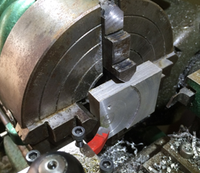 I started with a bit of scrap aluminium in my lathe chuck, which I cleaned up so I had a flat face to work with.
 I then prepared to machine out a 32mm hole, which was the size needed to fit over the front bearing housing.
 I turned a lot of solid aluminium into little curly bits of swarf to make that hole.
By the way, that is a DeWalt Extreme drill bit and they are just brilliant at making holes in metal. No pilot hole required for a 13mm bit, just plunge it straight in.
After drilling to 13mm, I used some larger bits to take it gradually out to 20mm and then a boring tool to open out to 32mm. It takes a while.
With the 32mm hole done, I then sketched the clamp shape onto the metal (just a rough free-hand sketch) and cut away most of what I didn’t need with a saw and file. This is way quicker than machining it.
I cut the split with a slitting saw on my mill but this could have been done with a standard hack saw. The chunk of metal left on to house the sensor was drilled to 7mm as close to the 32mm hole as possible (this should have been done before the 32mm hole was bored – oops! bad planning). I actually got it close enough to break into the 32mm hole, which was what I wanted.
The outside was then machined on my mill using a rotary table. Again this was unnecessary and could have just been filed to a reasonable finish. Finally, I drilled and tapped the hole to clamp the ring and another hole to fit the grub screw that secures the sensor.
The final result looks like this:
 OK I’ve used tools that not everyone has but bear in mind that apart from the 32mm hole, everything else could have been done with a hand held power drill, a hack saw and a file.
A nut and bolt could be used for the clamp and the sensor could be just glued in (the sensor is slightly tapered so once pushed in it gets to be a real tight fit in the 7mm hole).
 All this machining took ages on my lathe and mill (I’m no engineer) and at times I wish I’d just used a hose clamp!
Still, now it’s finished I’m glad I did it. Here it is, trial fitted to the motor.
The next job was to fit the magnet to the engine’s prop driver. The magnet is a 4mm cylindrical neodymium thing that will ferociously latch on to any nearby ironmongery. A 3.9mm drill bit is supplied with the kit. As I had a fully adjustable sensor position, I only had to concern myself with how far forward (i.e. towards the prop – away from the front bearing) the magnet needed to be.
As it happened, I needed to drill right at the point where there is a small step change in the prop driver’s diameter. This is easily dealt with however using a centre drill. This type of drill bit is very useful anyway if you are drilling into a circular item. An ordinary drill bit will have a tendency to wander off to one side. The centre drill stays true because it is very short and has a relatively large diameter shank except for the last few mm leading to the tip.
If you have access to a pillar drill and a vice
Getting the drill located centrally on a circular item is easily done with something like a short steel rule. Just lightly pinch the rule with the drill bit, if you’re bang on centre, the rule will be parallel to the vice jaws. If you’re a bit off to the right (as in the photo), then it will be angled down towards the vice jaws on that side.
 If you don’t have access to a pillar drill and a vice
I’m pretty sure nothing is super critical here and you can just do it by eye. If the magnet passes close to the sensor, it will fire the ignition. Having the magnet at a slight angle isn’t going to make much difference as far as I can see.
 Here’s the pilot hole drilled ready for the 3.9mm bit to follow.
I think the magnet was a bit over 4mm long so I drilled the 3.9mm hole to a depth of 5mm.
Again, not critical just make sure it’s deeper than the magnet. There’s loads of metal to play with.
After drilling, the next step is to press the magnet into the hole. Actually, before that happens, you must ensure that the magnet is the right way round. To do this, fit the spark plug into the cap and plug the battery into the CDI. Then holding the magnet in your fingers, just move it over the sensor. You will only get a spark when the correct end of the magnet is facing the sensor. Mark this end with a felt tip or something, then you’re good to press it in.
 Above, you can see I’m pressing the magnet in with my vice. I’m protecting the prop driver by using a soft jaw on that side of the vice. It required a considerable (and alarming) amount of force to press the magnet in but even a small vice would do the job.
 [Note: The rare-earth metals that these magnets are made of are very brittle. It cannot be hammered in because it will just shatter.]
- Comments(0) https://news.firebirds.org.uk/?p=69
