Blog Image

Firebirds Model Club News

4-Stroke Glow Engine to Petrol – Part 2

Workshop & Reviews Posted on Sun, August 09, 2015 08:54:40

Next up, the head shims had to be fitted. Six screws hold the head on [Note: One screw is between the valve rockers] so that came off in a jiffy.

The shims just sit between the head and the barrel. You actually need to fit them in the head first, it was just easier to get a photo of them sat on top of the barrel.

Getting the head back on was fairly easy but the push rods wouldn’t line up with the rockers for me so I ended up taking the rockers off (only one screw) and aligning everything carefully. None of this was difficult and took not many minutes at all.

Having shimmed up the head, the valve clearances were now huge, so they had to be brought back within tolerance (0.04mm-0.1mm). This is a simple matter of loosening the little lock nuts on the top of the rockers and then adjusting the screws down until the gaps are within tolerance. I checked the gap with a pair of feeler gauges (a 0.05mm and a 0.1mm). I managed to achieve a loose sliding fit on the thinner gauge and a tight fit on the thicker gauge. Again this only takes a short while.

The glow plug needs to be replaced with a spark plug. That was just the easiest job on this project.

The next job is the set the timing. The instruction pages that came with the CDI kit had an angle gauge printed on them so you just have to cut it out and stick it to some cardboard.

Just set the engine to Top Dead Centre and clamp the gauge up with the prop nut to read zero against some kind of fixed pointer.

The instructions said to set the timing between 28 and 30 degrees before TDC, so I set the angle to 29 degrees as my starting point. The prop driver and crankcase were marked at TDC and 29 degrees before TDC.

The sensor holder was then rotated so that it lined up with the magnet when the engine was at 29 degrees before TDC.

Finally here’s everything fitted together ready to run.

Down at the field the only trouble I had starting the thing was due to the fact that I mounted the tank way lower than the engine centre line. Once the fuel was drawn up she fired up fairly quickly.

After a short while I discovered that the back-pressure pipe to the tank needed a little clamp on it. The heat from the exhaust pipe made the Tygon tubing go very floppy and it fell off during running.

The engine ran at its best with the main needle ¾ of a turn out. The idle needle wasn’t altered from its glow setting.

The idle was good and throttle response was fine. At full throttle, she revved up to 8400 rpm on a 15×8 prop. I tried a degree of advance and retard on the timing but couldn’t improve on my first attempt at (or about) 28 degrees.

I have read that petrol conversions run hotter than glow motors because the methanol really cools the engine a lot. It certainly seemed hotter and I didn’t run it for that long so I shall have to ensure that there is extra cooling available when mounted in the plane.

The engine is destined for a Seagull Hawker Sea Fury I recently acquired.

One final note. The receiver, servos and associated leads must be kept as far away as possible from the ignition gear. It is advised that the throttle linkage is of the plastic snake variety to stop the RF noise finding its way in via a metal linkage. It’s not such a big issue with spread spectrum radio (e.g. Futaba FAAST or Spektrum DSMX) but 35MHz gear and lower spec. 2.4Ghz gear could suffer with interference from the ignition system unless care is taken. Apparently it was a particular problem with 72MHz radio but that doesn’t really affect UK fliers.


4-Stroke Glow Engine to Petrol – Part 1

Workshop & Reviews Posted on Sun, August 09, 2015 08:52:49

I had a go at converting a 4 stroke glow engine to run on petrol so I thought I’d write about my experience here. The first and obvious question is: “why do it at all?” Pete actually asked me this when I was trying to start the engine at the field.

To be honest I was more interested in the technical challenge than actually thinking about the benefits.

Here’s what I’ve read, for and against, on the subject:

For

1) Petrol is about 1/3rd the price of glow fuel.
2) The engine actually consumes about 1/2 as much petrol per minute as glow fuel. Meaning that the fuel is in effect about 1/6th the price.
3) A low and reliable tick over can be achieved.
4) It doesn’t splurge a load of oil residue all over your plane.
5) The added weight of the CDI + battery can be offset by using a much smaller fuel tank e.g. a 120 glow engine needs about an 18oz tank. With petrol you can go down to an 8-10oz tank – more than covering the CDI+batt weight.

Against

1) Petrol stinks
2) The conversion takes time and money (about £60).
3) The CDI unit+leads weighs 104g, and it has the power consumption of about 4-5 std. servos when they are operated in flight. Most people fit a separate battery so that’s another 100g.
4) The converted motor will make less power.
5) It adds complexity.
6) If you already run glow engines too, then you need separate fuel containers and pumps etc.
7) You need to pre-mix the fuel and oil yourself.

If you’re willing to put up with the smell, and the complication fuss (e.g. mixing your fuel and oil), then the main drawback is the lower power output. The main plus is the economics, especially for 120 and above engines.

The lower power output is a similar issue to the difference between two and four stroke glow engines e.g. A .46 two stroke is roughly equivalent (power-wise) to a .70 four stroke. The .70 weighs more so the plane’s aerodynamic performance drops slightly.

The difference between petrol verses glow power is not quite so large. From what I’ve read, a petrol engine will be 80% as powerful as the same size glow engine.

Given this, a petrol setup favours larger planes (say 120 and above) where the fuel savings are significant. It’s worth noting that there seems to be very few petrol four strokes out there. There are a couple of large Chinese 38cc motors at a good price and the almost fantastically expensive Saito petrol engines.

My Conversion Experience

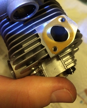
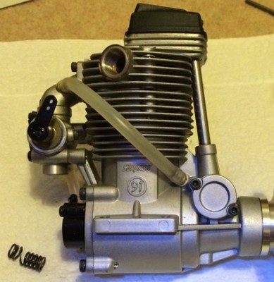
The motor I was planning to convert is an ASP 120 four stroke. It was well used but still felt smooth and had good compression.

I started by calling Just engines who sold all the necessary bits. My main concern was finding out whether the standard carburettor could be used. I was unsure as to whether a pumped carb might be required (as fitted to all the petrol engines I’ve seen so far). I was also worried that setting the needle valve might be difficult as mentioned in some posts I’ve read on the subject.

After asking a few questions about my motor, the man at Just Engines said that he expected the standard carb to work fine and advised at least trying it before buying a pumped carb and then having to make/buy an adapter to allow it to be fitted to my engine.

The parts needing to be purchased for the conversion were:
1) An ignition (CDI) system for glow plug motor (has a smaller plug cap)
2) A spark plug designed to fit the glow plug thread size.
3) A pair of shims to lower the engine compression. Not absolutely essential but recommended.

The only tricky part of the conversion is mounting the sensor that signals the CDI when to fire. The sensor supplied has a plastic housing with elongated mounting holes, which allow its position to be adjusted by a few degrees.

The picture shows this setup screwed to a ring that is on the outside of the engine’s front bearing housing.

I guess that because of the huge variation in crankcase design/sizes, a mounting ring isn’t supplied or available anywhere as far as I could tell. I’m not sure how this is secured to the engine either.

One quick method suggested in the instructions was to use a hose clamp (or jubilee clip), which I guess would work OK and doesn’t require special tools.

As I have machine tools, I decided to have a go at making my own clamping ring with a single screw to loosen/tighten for adjustment.

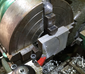
I started with a bit of scrap aluminium in my lathe chuck, which I cleaned up so I had a flat face to work with.

I then prepared to machine out a 32mm hole, which was the size needed to fit over the front bearing housing.

I turned a lot of solid aluminium into little curly bits of swarf to make that hole.
By the way, that is a DeWalt Extreme drill bit and they are just brilliant at making holes in metal. No pilot hole required for a 13mm bit, just plunge it straight in.
After drilling to 13mm, I used some larger bits to take it gradually out to 20mm and then a boring tool to open out to 32mm. It takes a while.

With the 32mm hole done, I then sketched the clamp shape onto the metal (just a rough free-hand sketch) and cut away most of what I didn’t need with a saw and file. This is way quicker than machining it.

I cut the split with a slitting saw on my mill but this could have been done with a standard hack saw. The chunk of metal left on to house the sensor was drilled to 7mm as close to the 32mm hole as possible (this should have been done before the 32mm hole was bored – oops! bad planning). I actually got it close enough to break into the 32mm hole, which was what I wanted.

The outside was then machined on my mill using a rotary table. Again this was unnecessary and could have just been filed to a reasonable finish. Finally, I drilled and tapped the hole to clamp the ring and another hole to fit the grub screw that secures the sensor.

The final result looks like this:

OK I’ve used tools that not everyone has but bear in mind that apart from the 32mm hole, everything else could have been done with a hand held power drill, a hack saw and a file.

A nut and bolt could be used for the clamp and the sensor could be just glued in (the sensor is slightly tapered so once pushed in it gets to be a real tight fit in the 7mm hole).

All this machining took ages on my lathe and mill (I’m no engineer) and at times I wish I’d just used a hose clamp!

Still, now it’s finished I’m glad I did it. Here it is, trial fitted to the motor.
The next job was to fit the magnet to the engine’s prop driver. The magnet is a 4mm cylindrical neodymium thing that will ferociously latch on to any nearby ironmongery. A 3.9mm drill bit is supplied with the kit. As I had a fully adjustable sensor position, I only had to concern myself with how far forward (i.e. towards the prop – away from the front bearing) the magnet needed to be.

As it happened, I needed to drill right at the point where there is a small step change in the prop driver’s diameter. This is easily dealt with however using a centre drill. This type of drill bit is very useful anyway if you are drilling into a circular item. An ordinary drill bit will have a tendency to wander off to one side. The centre drill stays true because it is very short and has a relatively large diameter shank except for the last few mm leading to the tip.

If you have access to a pillar drill and a vice

Getting the drill located centrally on a circular item is easily done with something like a short steel rule. Just lightly pinch the rule with the drill bit, if you’re bang on centre, the rule will be parallel to the vice jaws. If you’re a bit off to the right (as in the photo), then it will be angled down towards the vice jaws on that side.

If you don’t have access to a pillar drill and a vice

I’m pretty sure nothing is super critical here and you can just do it by eye. If the magnet passes close to the sensor, it will fire the ignition. Having the magnet at a slight angle isn’t going to make much difference as far as I can see.

Here’s the pilot hole drilled ready for the 3.9mm bit to follow.
I think the magnet was a bit over 4mm long so I drilled the 3.9mm hole to a depth of 5mm.

Again, not critical just make sure it’s deeper than the magnet. There’s loads of metal to play with.

After drilling, the next step is to press the magnet into the hole. Actually, before that happens, you must ensure that the magnet is the right way round. To do this, fit the spark plug into the cap and plug the battery into the CDI. Then holding the magnet in your fingers, just move it over the sensor. You will only get a spark when the correct end of the magnet is facing the sensor. Mark this end with a felt tip or something, then you’re good to press it in.

Above, you can see I’m pressing the magnet in with my vice. I’m protecting the prop driver by using a soft jaw on that side of the vice. It required a considerable (and alarming) amount of force to press the magnet in but even a small vice would do the job.

[Note: The rare-earth metals that these magnets are made of are very brittle. It cannot be hammered in because it will just shatter.]


Seagull Edge 540

Workshop & Reviews Posted on Thu, May 07, 2015 19:44:22

Justin has very kindly written an article for this section on his Seagull Edge 540.

The Seagull Edge 540 is a mid-wing sports aerobatic plane advertised as 46 size but more on that later.

This was my first all-out sports model and was purchased as my fourth plane but would make an ideal choice as a third plane after the traditional high & low wing trainers have been mastered.

The ARTF build was straightforward with no real issues.

The fittings supplied were of a good standard and the only mods I made were to fit a larger Du Bro fuel tank, fit rubber wheels, add a support to the rudder push rod to prevent blow back during knife edge flight and to fabricate a piano wire undercarriage.

Build of the fuselage and wings is the normal seagull good quality being a bit more robust than some manufacturers but therefore slightly heavier, ideal for the club flyer.

In the air on low rates it handles nicely, it will stall if pushed but general low speed handling is nice and predictable. On high rates it’s great and will do the majority of pattern aerobatic manoeuvres and holds its own with more expensive airframes.

Newsletter scribe Geoff Scott had one of these (as my third model – ed.) before me and had originally fitted a 46 two stroke as per the manufacturers recommendations, this turned out to be very underpowered and the engine was swapped for the same Irvine 53 two stroke motor that I have in mine. It fly’s well on the 53 but we are both of the opinion that a 60 size two stroke would be the perfect choice.

I’ve had this model for a few years now and still fly it regularly, it still seems to be available in some of the online shops and at a tad over £100 it’s a really good buy and comes highly recommended.


OS 91 Valve Spring Failure

Workshop & Reviews Posted on Thu, May 07, 2015 19:35:26

I had an odd failure on the 14th of Feb when I tried to start my new favourite plane (the Great Planes Skybolt) ready for its fourth flight of the day. As usual, I wound the prop backwards until it was against compression before applying my starter. However, I was surprised to find that there was now no compression at all from this nearly new OS 91.

After doing basic checks on the glow plug and valve rockers (by removing the rocker cover) and finding nothing apparently wrong, I decided to give up and took her home.
When I got the plane apart at home, I discovered that the intake valve was not operating correctly. It wasn’t springing back up, at least not fully. The engine head was removed and the spring extracted. It was in two pieces.

This was not a failure mode I’ve come across during my short time in the modelling world. I was very surprised, especially as this engine is nearly new.

I expect that most are familiar with the process of removing valves but if like me you’ve never done it before, then what you have to do is support the valve from underneath (I just used a finger but wood is a good alternative), then compress the valve spring by pressing down on the retainer cap.

This will allow the two tapered collet halves to drop out. However, because the collet halves have a fairly gentle taper, they grip the retainer cap and I was unable to push hard enough with my remaining fingers to release it. I ended up using an M3 nut driver to push down on the retainer, which popped down with quite a snap as the taper released. Using the nut driver also had the advantage of catching the two collet halves before they flew off somewhere.

In the picture above you can see the now empty intake valve guide on the left and the assembled exhaust valve on the right.

A new spring was purchased from Just Engines and cost about £2.50 I think. Trouble is they had a minimum order price of about £6 so I bought some other little bits and got it all delivered within two days.

Reassembly was fun. I was able to hold the valve spring and its retainer cap down while holding the valve itself up using my fingers but this only left my face available to put the collet halves back in. If I took one hand away, I couldn’t hold the spring retainer down long enough or with enough stability to get the collets on.

I needed a spring compressor. After a couple of minutes thought I wondered if the threaded hole used to secure the rocker cover could help me out.

It was very close to the valves, so I thought that a screw with a washer could be used to press on the spring retainer.

In the picture you can see the arrangement that worked for me (taken after I got the valve assembled). As the screw was one of the actual rocker cover screws, it was a bit long for this job, hence the nut and other washers acting as spacers.

It’s not ideal of course because it’s only pressing on one side of the retainer. Initially, the retainer and spring tried to escape sideways from under the washer so I used my thumb on the other side to stabilise it. Of course this method also compressed the exhaust valve spring too (forcing the valve down a bit) but that didn’t matter.

Once the spring is compressed far enough, the valve guide tube prevents the arrangement moving sideways. This was all done with the valve in its guide but just resting on the work surface. Frankly, it could have been left out altogether. Once the spring was compressed far enough, the valve was pushed up and the tiny, tiny little collet halves were placed and held (by finger and thumb) in the groove. The screw was then wound out, which allowed the retainer to ride up and encapsulate the collet halves.

All that remained was to reassemble the top end of the engine. During this process, I was slightly bemused by the gasket on the intake tube. It doesn’t matter which of the four possible orientations you use, it just doesn’t match the shape of the port and the location of the mounting screws. Who designed that?

The reassembly went smoothly and compression has now returned.


HobbyKing Zlin Z50L

Workshop & Reviews Posted on Thu, May 07, 2015 19:11:40

Buying an airframe from HobbyKing can be real hit and miss affair so I thought it worth writing about my experience.

Here are the specs as stated by HobbyKing:
Wingspan: 1612mm (Just over 63”)
Length: 1403mm
Dry Weight: 1672g
Flying Weight: 2350g (Just over 5lb. Hmmm…really? try 3Kg – 6.5lb)
Price £103.22

It can be powered by a 0.70 glow engine or 50mm Brushless Outrunner Motor.
Full details here:
http://www.hobbyking.com/hobbyking/store/__26002__Zlin_Z_50L_1612mm_0_70_class_Glow_EP_Sport_Scale_ARF_UK_Warehouse_.html?strSearch=zlin

When the kit arrived the overall fit and finish looked great. However, I did quickly noticed that the covering lifted easily at quite a few places on the edges. Still, I thought the iron would take care of that.

My original plan was to install an electric setup in this plane. I already had a suitable motor and speed controller. I changed this to IC when I hit a second snag. I’ll detail this in a moment, just a few comments on the build first.

Construction is fairly straightforward. The wing has a subtle dihedral and has to be permanently joined into a one-piece wing. The only possible pitfall I can see here is getting the dihedral brace the wrong way up.

All control surfaces use the fabric like hinges that soak up the CA. The slots are nicely pre-cut and it all goes together sweetly. There’s a ton of movement available on every surface ant they are all quite large too.

The aileron servos are mounted on the inside of panels that are then screwed to the wings. I like this arrangement because it is very neat. It did cause me a slight headache because the arms supplied with the standard servos (these) I was using throughout the plane were too short.

I bought a pair of alloy arms (these) and then file down the thickness so that it would fit through the slot. After the first flight, I moved the linkage to the inner one of the two holes in the servo arm. This still gives huge aileron throws and the plane is very lively on full rates.

The fuselage all went together very nicely all tail parts were nice and square, the canopy, cowl and wing-fuselage fit are all excellent. Rudder is pull-pull and elevator is on a single long pushrod (elevator halves are joined by a ‘U’ shaped wire.). So all servos are up front. The exit holes for all the control linkages are very neat and preserve the lines of the plane.

The problems started when I got to the power plant side of things. I had intended to use my NTM 42-58 motor (another HobbyKing purchase from a while back). I also had suitable batteries – 6s 4000mah.
I temporarily screwed the motor in place and put a battery in to see if the C of G would be OK. It wasn’t. It was about 50mm behind the target 118mm from the leading edge.

I put a heavy metal spinner on the nose, then I placed a 6s 2800mah battery on top of the 4000mah one.
Now the C of G was about 20mm behind the target position and the all-up-weight was getting high.
At first, I didn’t know what to do. How was I going to achieve the correct C of G without ending up with a 4Kg plane? Then I remembered that I had a new ASP 65 four stroke (bought at a Firebirds auction for £35). The reason I hadn’t installed it anywhere was because it’s not a great motor. It’s a 90 sized crankcase effectively under-bored with a 65 piston liner setup. This made the motor heavy for its power output.

I thought maybe this was a good candidate for the Zlin. The advantage (in this case) of I/C power is that all the weight in concentrated right up front in the engine, rather than mostly in the battery, which sits further back in the fuel tank area.

So I headed down the ASP 65 route. I mounted the engine horizontally and the room in the cowl was such that the rocker cover only just pokes out the side. The exhaust is fully contained and needed a silicone extension to get the exhaust snot outside the plane. The main needle pokes out the top and needs to be removed to get the cowl off.

Oh yeah, I also mounted the engine and cowl as far forward as possible. Such that the cowl doesn’t quite meet the fuselage at the bottom.

Despite the four stroke iron mongery up front, I still needed a lot of extra weight to balance the plane. I discovered that a 2S 4000mah LiPo (sibling of the one that exploded a while back) provided the necessary weight as long as it was fitted within the cowl. I also fitted a nice shiny aluminium spinner because that weighed 125g.

Finally! The C of G was achieved, although lifting the plane into the car was a challenge.
Guess what? The first flight revealed that the plane was very nose heavy. The spinner was swapped out for a plastic one, saving about 95g. Still nose heavy. The 4000mah LiPo was swapped for a 2000mah LiPo (saving about 100g), still nose heavy. It’s beginning to look like I could have had the setup I originally wanted now. Grrrrrr…..

I currently have the C of G set at 138mm from the leading edge. From the way it handles now, I reckon it could go back at least another 5mm or so.

Currently, loops, rolls, stall turns are fine. The knife edge requires quite a bit of work though. I have to hold a lot of up elevator and in one direction, I have to fight the plane’s desire to roll to inverted. I cannot get it to spin at all on rudder/evelator only.

At 3Kg, the all up weight is substantially higher than the advertised flying weight. However, 3Kg is a very reasonable weight for a plane this size and the low speed handling is superb, ‘floaty’ in fact.
In conclusion, I’m fairly happy with the Zlin. With it’s £3 servos, £35 engine and £103 airframe, it has been a cheap plane to build and flies well enough to keep me amused.

PS: I snapped off the undercarriage on a rough landing and it has been broken off twice since then, on much less harsh landings. The problem is not the vertically delivered shock of a hard landing, it’s the horizontal forces ripping the wheels backwards (say when you run into the long grass at the end of the strip). The rigid aluminium undercarriage transmits all the shock to the woodwork, which is way to flimsy to deal with it.

I have now fitted the exact same undercarriage arrangement that you get in a typical trainer, i.e. a torque wire arrangement that allows the wheels to be flexed upward and backward without tearing the arse out of your model.


Staufenbeil Taylorcraft Review

Workshop & Reviews Posted on Wed, May 06, 2015 21:21:11

I have had this model for over a year but have only just got around to flying the maiden. A combination of last year’s incessant bad weather, electronic glitches and my own nervousness following one or two ‘eventful’ maidens on other models had been putting me off. As it turned out, the maiden was a complete non-event after a few clicks of trim she was flying beautifully and instantly became my new favourite plane.

The model itself is an ARTF produced by Flight-Model and sold by Staufenbeil in Germany, who made my decision to purchase easy by offering free shipping to the UK. The airframe components are nicely constructed in a traditional combination of lite ply, balsa and Oracover film. The design is intended for electric power only and has it been constructed correspondingly light with a wing loading of around 21 oz per sq ft.

The basic particulars are:
Wingspan: 222cm (87 inches)
Wing area: 70dm2 (7.5 sq ft)
Length: 143cm (56 inches)
Flying weight: 4.5kg (159 oz)

The build was straight forward, the only real complication being finding space in the house big enough to assemble it! My usual building room is only 6 inches wider than the model’s wingspan meaning that if was impossible to get the wings on over the wing tube so final stages of the build were done in the spare bedroom.

Propulsion is provided by a 6s LiPo and an Eflite Power 60 turning a 16×8 prop, giving around 5kg of thrust and 1000 watts of power at full throttle. I fitted high torque digital metal gear full size servos (TowerPro). Receiver power comes from the ESC’s in built BEC (Castle Creations 100 Amp). To provide some redundancy to the receiver power, I have fitted a Scorpion Backup Guard. This is a neat little device that monitors the receiver voltage and incorporates it’s own battery which will kick in in the event of failure of the main supply, hopefully preventing any chance of losing control.

The model’s flying characteristics are very docile making this a relaxing and enjoyable model to fly. The light wing loading and ample power combine to make the take off easy, full throttle will see the model airborne after a few feet so throttle moderation is required for a more scale-like take off!

As is typical of these high wing types, rudder is needed in the turns to stop the tail from dropping. This could be mixed in on the radio but I prefer to add rudder manually. The relatively large control surfaces mean there is plenty of authority and mild aerobatics are certainly within the model’s capabilities. Flight times of over 15 minutes are possible on a 5000mAh battery so there is plenty of time in the air to practice these manoeuvres, or just stooge around doing nice scale like passes. Landings are again helped by the low wing loading and the model can be slowed right up for a gentle touch down.

The Taylorcraft is a lovely looking plane, the lines of which are captured well by this model. The larger size of the model certainly gives it presence both on the ground and in the air. Electric models of this size are still relatively uncommon and I have received a few surprised comments from people expecting to find one of those noisy IC engines under the cowl!


VQ FW 190 review

Workshop & Reviews Posted on Wed, May 06, 2015 21:02:26

VQ do a range of 60″ ish span warbirds that retail for about £100 each. The fit, finish and overall quality is reasonable but not great, par for the coarse given the price I guess. Build was straightforward. Scale wise it is very much a stand-off plane, in fact, stand-way-off. It’s at its best in the air.

I fitted standard Futaba 3003 servos and set the throws indicated by the manual. This gives a nice slow roll and smooth manoeuvres. She’s had plenty of hard landings and luckily for me, the airframe has proven to be quite tough. I have flown this most of the good weekends over the 3½ years that I owned it and I can tell you that it is an excellent flier. I have also flown the ME 109 from the same VQ range, which is also a great flier. The FW 190 comes in at 3Kg. I seem to remember the ME109 was about 2.7Kg on similar wing area.

The pilot figure is a bit special, having been expertly painted by Firebirds own artist John H. Who really is an expert in this field having painted many battalions of war game figures. John gave a club talk on this subject a while ago and many useful tips were given. John painted this figure and donated it for the club’s Christmas raffle, which I was lucky enough to win.

I decided to fit a used OS 70-FS, purchased from the HMFA Great Southern Auction (I think it was £70). Before I fitted the motor, it was bench run (down at the club) and I had quite a problem with fuel feed and breather pipes. Lots of people helped me out (Dave, Roger & Russell among others) and we eventually blanked off the pipe that ran from the crank case to the exhaust. This cured all running problems so she was fitted to the FW190 and it has run nicely ever since. The 70 sized four stroke is an ideal match for this plane giving plenty of power.

During one flight at Beaulieu the fuel tank bung fell out, partially soaking the tank bay area with fuel. Upon inspection, the bung opening was so rough that the bung did not fit properly. This was simply fixed with an aftermarket tank.

When I bought the plane, I also bought the optional VQ retracts to go with it. Mechanically, given the price, these worked very well. The only problem being that the wheels were a little too far aft of the wing LE and the plane kept nosing over (on take-off and landing). A lot of landings required that the U/C wire be straightened slightly to avoid binding on the next flight.

After a few months, I bit the bullet and decided to swap the VQ mechanical retracts for some HobbyKing (£7) servoless retracts plus the Oleos from HK too. They don’t just drop in, I had to do a bit of butchery on the mounting to make them fit. I also took the opportunity to mount them with the leg angled forward to stop the annoying nose-overs on landing.

Having now had quite a few landings on these, I can vouch for them as being a good cheap U/C on a plane this size. I have so far collapsed two of them by turning too sharply (at speed) on landing. The sideways force on the leg being pushed inwards breaks something (plastic gears I guess) and then you need a new one. The Oleos are sprung with no damping, so some landings look like Zebadee is in control.

Summary
Pros:
• An excellent flyer for not a lot of money that has weathered well after a lot of use and abuse.
• Solidly built but not overly heavy. The fully sheeted fuselage has withstood some very heavy landings including at least one belly landing.
Cons:
• VQ seem to use an unusual covering material (vinyl I think) that pulls apart the seams in the hot sun. This slackens the covering and you then cannot shrink it tight again
• Some of the hardware was a bit suspect e.g. the fuel tank bung that fell out.
• No spares available – e.g. My broken spinner cannot be replaced.