Solo Qualifiers
Congratulations to Tony and Matt who have both achieved their solo qualification in January. Let’s
hope we have some good weather in 2015 so that they can build up their
experience without too many crashes on the way!

Solo Qualifiers
Congratulations to Tony and Matt who have both achieved their solo qualification in January. Let’s
hope we have some good weather in 2015 so that they can build up their
experience without too many crashes on the way!
Justin has very kindly written an article for this section on his Seagull Edge 540.

The Seagull Edge 540 is a mid-wing sports aerobatic plane advertised as 46 size but more on that later.
This was my first all-out sports model and was purchased as my fourth plane but would make an ideal choice as a third plane after the traditional high & low wing trainers have been mastered.
The ARTF build was straightforward with no real issues.
The fittings supplied were of a good standard and the only mods I made were to fit a larger Du Bro fuel tank, fit rubber wheels, add a support to the rudder push rod to prevent blow back during knife edge flight and to fabricate a piano wire undercarriage.
Build of the fuselage and wings is the normal seagull good quality being a bit more robust than some manufacturers but therefore slightly heavier, ideal for the club flyer.

In the air on low rates it handles nicely, it will stall if pushed but general low speed handling is nice and predictable. On high rates it’s great and will do the majority of pattern aerobatic manoeuvres and holds its own with more expensive airframes.
Newsletter scribe Geoff Scott had one of these (as my third model – ed.) before me and had originally fitted a 46 two stroke as per the manufacturers recommendations, this turned out to be very underpowered and the engine was swapped for the same Irvine 53 two stroke motor that I have in mine. It fly’s well on the 53 but we are both of the opinion that a 60 size two stroke would be the perfect choice.
I’ve had this model for a few years now and still fly it regularly, it still seems to be available in some of the online shops and at a tad over £100 it’s a really good buy and comes highly recommended.
When running an IC engine or electric motor much above tick-over we know it’s prudent to stand behind the prop in case something ‘lets go’. If you’re anything like me, then you will observe this simple precaution most of the time but just occasionally you’ll stay in front of your own or someone else’s model while you/they rev the nuts off it. Should it all go wrong, then the engine might not be the only thing to lose its nuts.
The snag is that props don’t come off that often, which is really a good thing I suppose, but it can make you a bit blasé about taking precautions. I have recently had two incidents where the prop, complete with spinner, came off and hurtled away at great speed from the rest of the model.
On the first occasion, I was testing a Saito 115 four stroke engine and had already had the prop on and off a couple of times. I guess I had not done the locking nut up tightly enough and the whole lot flew off at near full power. It flew forward in a nice straight line and struck the ground about 6 metres away. It then careened into a trellis and a fence, coming to rest nine metres away (a nicely rounded 3 fence panels).
On the second occasion (Easter Sunday), a failed E-clip meant that the rotor housing and shaft of the electric motor I was testing, joined forces with the prop and spinner for their brief and wild excursion. The rear wheel of Matt’s Landover put an end to their travel ambitions. I guess they travelled about 4-6 metres.
Both motors were swinging 15” props, which are certainly capable of inflicting deep and nasty cuts.
Another reason not to stay in front is that there is also a possibility that the whole aircraft might escape its restraint. Of course I’m just reinforcing what we have all been taught, understand and practice pretty well really. I just think it’s good to have the occasional refresher.
PS: I replaced the E-clip and made a collet that screwed into a flat I ground into the shaft. That should hold the bleeder on.
I had an odd failure on the 14th of Feb when I tried to start my new favourite plane (the Great Planes Skybolt) ready for its fourth flight of the day. As usual, I wound the prop backwards until it was against compression before applying my starter. However, I was surprised to find that there was now no compression at all from this nearly new OS 91.

After doing basic checks on the glow plug and valve rockers (by removing the rocker cover) and finding nothing apparently wrong, I decided to give up and took her home.
When I got the plane apart at home, I discovered that the intake valve was not operating correctly. It wasn’t springing back up, at least not fully. The engine head was removed and the spring extracted. It was in two pieces.
This was not a failure mode I’ve come across during my short time in the modelling world. I was very surprised, especially as this engine is nearly new.
I expect that most are familiar with the process of removing valves but if like me you’ve never done it before, then what you have to do is support the valve from underneath (I just used a finger but wood is a good alternative), then compress the valve spring by pressing down on the retainer cap.

This will allow the two tapered collet halves to drop out. However, because the collet halves have a fairly gentle taper, they grip the retainer cap and I was unable to push hard enough with my remaining fingers to release it. I ended up using an M3 nut driver to push down on the retainer, which popped down with quite a snap as the taper released. Using the nut driver also had the advantage of catching the two collet halves before they flew off somewhere.
In the picture above you can see the now empty intake valve guide on the left and the assembled exhaust valve on the right.
A new spring was purchased from Just Engines and cost about £2.50 I think. Trouble is they had a minimum order price of about £6 so I bought some other little bits and got it all delivered within two days.
Reassembly was fun. I was able to hold the valve spring and its retainer cap down while holding the valve itself up using my fingers but this only left my face available to put the collet halves back in. If I took one hand away, I couldn’t hold the spring retainer down long enough or with enough stability to get the collets on.
I needed a spring compressor. After a couple of minutes thought I wondered if the threaded hole used to secure the rocker cover could help me out.

It was very close to the valves, so I thought that a screw with a washer could be used to press on the spring retainer.
In the picture you can see the arrangement that worked for me (taken after I got the valve assembled). As the screw was one of the actual rocker cover screws, it was a bit long for this job, hence the nut and other washers acting as spacers.
It’s not ideal of course because it’s only pressing on one side of the retainer. Initially, the retainer and spring tried to escape sideways from under the washer so I used my thumb on the other side to stabilise it. Of course this method also compressed the exhaust valve spring too (forcing the valve down a bit) but that didn’t matter.
Once the spring is compressed far enough, the valve guide tube prevents the arrangement moving sideways. This was all done with the valve in its guide but just resting on the work surface. Frankly, it could have been left out altogether. Once the spring was compressed far enough, the valve was pushed up and the tiny, tiny little collet halves were placed and held (by finger and thumb) in the groove. The screw was then wound out, which allowed the retainer to ride up and encapsulate the collet halves.
All that remained was to reassemble the top end of the engine. During this process, I was slightly bemused by the gasket on the intake tube. It doesn’t matter which of the four possible orientations you use, it just doesn’t match the shape of the port and the location of the mounting screws. Who designed that?
The reassembly went smoothly and compression has now returned.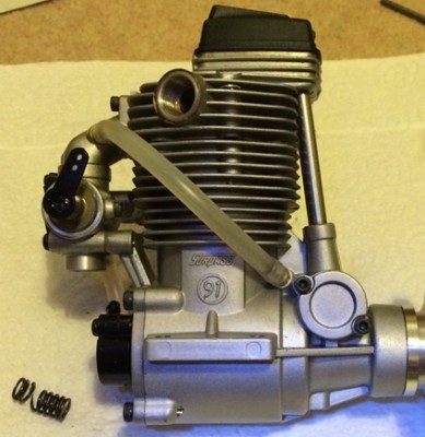
Once again we have a LiPo battery charging horror story that did result in a fire and very nearly a significant one.

It all started when the blue and silver charger near the centre of the picture was being used to charge the Turnigy Orange TX directly in front of the charger. OK, I hear you saying “what Orange TX?” Well, it’s that rectangular mess that is actually just the PCB and a few miscellaneous components that weren’t completely annihilated by the fire.
Further towards the front of the bench and to the right we have a few more lipos that were either pre, post or actually on charge. They were also destroyed and of course added fuel/heat to the fire.
The circular item near the front left is the remains of a Lander EDF unit. Only the aluminium part remains, all the plastic bits melted/burned away.
Near the top right a blue upright aerosol type can is visible. This is a can of gas for a blow torch. Shelving units immediately to the left (not in the above picture) also house a can of blow torch gas. Add to that a garage full of foam models, various glues, solvents and paint products and it’s a wonder he didn’t end up with a Fukushima style accident.
Fortunately, the fire did burn itself out. The MDF worktop seems to have inhibited rather than added fuel to the fire. There must have been some serious heat so I was impressed that it didn’t burn.
Directly above the charging Orange TX was a brand new Spektrum DX 9. This suffered some heat damage (partially melted handle) and a fair amount of smoke damage but is still quite usable.
Pete is unsure of exactly what transpired but he’s guessing that the Orange TX batteries may have been very low before they went on charge (having been using them quite a bit that day). It was an old battery and it is possible that the TX was left switched on before charging commenced.
As with my own fire/explosion experience a few months back, this event reinforces the fact that LiPos really don’t like being discharged below a certain threshold and get angry if they are.
The insurance company inspected the damage and did pay a reasonable sum to compensate for the damage to the garage and the model gear within.
Builders were organised and work commenced on a new garage interior. As it happens the builders didn’t seem to be qualified to deal with anything more complex than a hammer. They actually managed to add to the damage by smashing a glass door panel. After some bungled plasterboard work, Pete decided to do the repairs himself. The insurance ended up paying a little extra for that.
All the garage work has now been completed and includes a new, more fire resistant charging area. The opportunity for a Spring Clean wasn’t missed too, so a lot of rubbish went off to the landfill.
Pete has added new Orange and Spektrum DX8 TXs to his fleet.
Pete said that his main lesson learned was to not leave LiPos unattended during charge. We’ve all done it but it’s a bad habit that the manufacturers themselves advise against.
Many thanks to Geoff our Safety officer for the following article.
A little story from about 35 years ago this month (I know, I know, I’m slowly turning into a sad old git).
In the early days of electric flight I was lucky (if that’s the word) to assist in some small way with evaluating the very first commercial electric r/c model to come onto the market. Our local model shop in Portsmouth was run by Ray and Audrey Brown. Now Ray was a brilliant and highly skilled modeller; some of you may remember his highly successful “Chevron”, kitted by Model Flight Accessories. Through his connection with MFA he was given a pre-production kit to check out. It was a cute little high wing model called the Hummingbird and amazingly it was electric! It featured a Mabuchi 540 brushed motor, 8 cell NiCad pack, and a servo operated on/off switch for motor control!
It was hopelessly under powered, and Ray managed a couple of flights just about staggering around the patch. A couple of days later in the shop, Ray, now a bit disillusioned, handed the whole thing over to me to see if I could do anything with it as MFA were hoping for some feedback. A quick check of the battery pack showed that one cell was a bit down so we replaced it ready to try again.
It’s interesting to reflect at this point that in these early days of commercial electric flight the real danger was perceived to be the unvented NiCad cells. If the battery heated up too much, either through discharging too far (no automatic cut out in those days) or by overcharging, there was nowhere for the expanding electrolyte to go, so the batteries exploded! I witnessed this a few years later, and it happened after the flight with the model just sitting on the ground doing nothing. Very impressive, and very little left! Fortunately it was about 20 ft away from anyone.
Anyway, back to the Hummingbird. With a fully charged pack and ready to leave for the field I decided a quick check was in order. Now for some reason I took it into my head that the best place to do this was on the bed. . . . . . . .
Now a nice soft bed is not really the best place to stand a transmitter up on. Before I had a chance to grab it, it had toppled forward, ever so slightly moving the throttle stick, but just enough to operate the motor ON switch in the model.
It was at this point that the really big difference between IC and electric became violently obvious! Ever wondered what they put in all the little pockets of a Duvet? (I’m sure we used to call them “continental quilts”?) I found out very quickly because the room was soon full of it!
Fortunately, and I’m not sure how, I didn’t get injured grabbing anything and managed to stop the motor, but the damage to the bed was extensive. Every time I power up an electric model I remember this little incident, and so far it has stopped me doing anything stupid!
So what are the lessons? According to the latest BMFA figures an increasing number of personal injuries are now related to electric power systems. I’m convinced that none of these would happen if a few simple rules are adhered to.
Firstly, at home on the bench.
1. Modern speed controllers are designed to be more or less idiot proof, but they can go wrong! If you are setting up a model NEVER do it with the prop fitted. The most common scenario is to have the throttle reversed. If you’ve done this, even if you realise what has happened it is very difficult to convince yourself that the throttle needs to go the wrong way to stop the motor! No prop = no damage. Don’t run the motor with the prop fitted in the workshop unless you have plenty of clear uncluttered space. Better still, take it out in the garden.
Secondly, at the field.
1. Even if the transmitter throttle is in the wrong position modern speed controllers should not start the motor until the throttle has been cycled to arm the system, but apparently this can go wrong, so ALWAYS have it in mind that the prop might start spinning the instant you connect the battery. Hold the model securely and get behind it when you connect the battery. If the model has retracts make sure the transmitter switch is in the correct position!
2. The design of some battery compartments is such that the battery has to be fitted from the front, through the propeller arc, often with the model on its back. By far the safest way here is to fit a shorting plug such that the final connection is only made with the plane upright, but if this is not practical it’s often possible to wedge the prop firmly on the ground; If it does try to start the worst will probably be a burned out speed controller, although arguably it will already be damaged to allow this to have happened, so you’ll not have lost anything!
3. Once the model is ready for flight it is potentially capable of injury. Assume it could start on its own and treat it accordingly. If you use a transmitter tray be particularly careful when putting the straps over your head – it is SO easy to knock the throttle stick up. . . .
4. After flight, the FIRST thing to do when the model is clear of the strip is to disconnect the battery. NEVER leave a “live” model in the pits unattended.
Having hopefully taken all that in, you might be wondering what became of the little Hummingbird? Well, it survived with nothing more than a broken prop and although by today’s standards its flight envelope might best be described as “barely adequate” it did fly quite well and went into full production.
When the battery pack failed again after about thirty flights I gave up and fitted an Enya .09 and it was eventually retired fuel soaked about five years later. I can’t help thinking that if they had sold it as IC from the start it might have done better, but that would have been boring!
Attached is a PDF file containing the slides of a talk by Paul (one of our members) on how to setup and trim a fixed wing model aircraft.


Buying an airframe from HobbyKing can be real hit and miss affair so I thought it worth writing about my experience.
Here are the specs as stated by HobbyKing:
Wingspan: 1612mm (Just over 63”)
Length: 1403mm
Dry Weight: 1672g
Flying Weight: 2350g (Just over 5lb. Hmmm…really? try 3Kg – 6.5lb)
Price £103.22
It can be powered by a 0.70 glow engine or 50mm Brushless Outrunner Motor.
Full details here:
http://www.hobbyking.com/hobbyking/store/__26002__Zlin_Z_50L_1612mm_0_70_class_Glow_EP_Sport_Scale_ARF_UK_Warehouse_.html?strSearch=zlin
When the kit arrived the overall fit and finish looked great. However, I did quickly noticed that the covering lifted easily at quite a few places on the edges. Still, I thought the iron would take care of that.
My original plan was to install an electric setup in this plane. I already had a suitable motor and speed controller. I changed this to IC when I hit a second snag. I’ll detail this in a moment, just a few comments on the build first.
Construction is fairly straightforward. The wing has a subtle dihedral and has to be permanently joined into a one-piece wing. The only possible pitfall I can see here is getting the dihedral brace the wrong way up.
All control surfaces use the fabric like hinges that soak up the CA. The slots are nicely pre-cut and it all goes together sweetly. There’s a ton of movement available on every surface ant they are all quite large too.
The aileron servos are mounted on the inside of panels that are then screwed to the wings. I like this arrangement because it is very neat. It did cause me a slight headache because the arms supplied with the standard servos (these) I was using throughout the plane were too short.
I bought a pair of alloy arms (these) and then file down the thickness so that it would fit through the slot. After the first flight, I moved the linkage to the inner one of the two holes in the servo arm. This still gives huge aileron throws and the plane is very lively on full rates.
The fuselage all went together very nicely all tail parts were nice and square, the canopy, cowl and wing-fuselage fit are all excellent. Rudder is pull-pull and elevator is on a single long pushrod (elevator halves are joined by a ‘U’ shaped wire.). So all servos are up front. The exit holes for all the control linkages are very neat and preserve the lines of the plane.
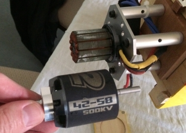
The problems started when I got to the power plant side of things. I had intended to use my NTM 42-58 motor (another HobbyKing purchase from a while back). I also had suitable batteries – 6s 4000mah.
I temporarily screwed the motor in place and put a battery in to see if the C of G would be OK. It wasn’t. It was about 50mm behind the target 118mm from the leading edge.
I put a heavy metal spinner on the nose, then I placed a 6s 2800mah battery on top of the 4000mah one.
Now the C of G was about 20mm behind the target position and the all-up-weight was getting high.
At first, I didn’t know what to do. How was I going to achieve the correct C of G without ending up with a 4Kg plane? Then I remembered that I had a new ASP 65 four stroke (bought at a Firebirds auction for £35). The reason I hadn’t installed it anywhere was because it’s not a great motor. It’s a 90 sized crankcase effectively under-bored with a 65 piston liner setup. This made the motor heavy for its power output.
I thought maybe this was a good candidate for the Zlin. The advantage (in this case) of I/C power is that all the weight in concentrated right up front in the engine, rather than mostly in the battery, which sits further back in the fuel tank area.
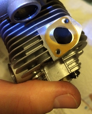
So I headed down the ASP 65 route. I mounted the engine horizontally and the room in the cowl was such that the rocker cover only just pokes out the side. The exhaust is fully contained and needed a silicone extension to get the exhaust snot outside the plane. The main needle pokes out the top and needs to be removed to get the cowl off.

Oh yeah, I also mounted the engine and cowl as far forward as possible. Such that the cowl doesn’t quite meet the fuselage at the bottom.
Despite the four stroke iron mongery up front, I still needed a lot of extra weight to balance the plane. I discovered that a 2S 4000mah LiPo (sibling of the one that exploded a while back) provided the necessary weight as long as it was fitted within the cowl. I also fitted a nice shiny aluminium spinner because that weighed 125g.
Finally! The C of G was achieved, although lifting the plane into the car was a challenge.
Guess what? The first flight revealed that the plane was very nose heavy. The spinner was swapped out for a plastic one, saving about 95g. Still nose heavy. The 4000mah LiPo was swapped for a 2000mah LiPo (saving about 100g), still nose heavy. It’s beginning to look like I could have had the setup I originally wanted now. Grrrrrr…..
I currently have the C of G set at 138mm from the leading edge. From the way it handles now, I reckon it could go back at least another 5mm or so.
Currently, loops, rolls, stall turns are fine. The knife edge requires quite a bit of work though. I have to hold a lot of up elevator and in one direction, I have to fight the plane’s desire to roll to inverted. I cannot get it to spin at all on rudder/evelator only.
At 3Kg, the all up weight is substantially higher than the advertised flying weight. However, 3Kg is a very reasonable weight for a plane this size and the low speed handling is superb, ‘floaty’ in fact.
In conclusion, I’m fairly happy with the Zlin. With it’s £3 servos, £35 engine and £103 airframe, it has been a cheap plane to build and flies well enough to keep me amused.

PS: I snapped off the undercarriage on a rough landing and it has been broken off twice since then, on much less harsh landings. The problem is not the vertically delivered shock of a hard landing, it’s the horizontal forces ripping the wheels backwards (say when you run into the long grass at the end of the strip). The rigid aluminium undercarriage transmits all the shock to the woodwork, which is way to flimsy to deal with it.
I have now fitted the exact same undercarriage arrangement that you get in a typical trainer, i.e. a torque wire arrangement that allows the wheels to be flexed upward and backward without tearing the arse out of your model.
Take a look at this melted Nimh battery from a Spektrum DX8 transmitter.

This one belongs to Terry. Paul A. is also familiar with this situation because he had one melt too. In fact his battery looked worse than this.
Having looked around on the internet, it’s a common problem.
The cause? Overcharging. It turns out that the DX8 charging circuitry has no means to shut off the charge current as the battery reaches capacity and starts to heat up.
Overheating is not normally a problem at the low charge currents (typically about 100-200mA) used by the little wall plug chargers. The reason being that the battery can easily dissipate the heat as it is charging.
That is until you factor in the shrink wrapped battery pack, surrounded by foam packing that is inside a plastic box. Then heat dissipation becomes much more difficult.
The foam packing is in there because Spektrum also sell a larger battery for this TX, which is a 4000mah LiPo not a 2000mah Nimh. When installing the LiPo, the foam has to be discarded to make way for this larger battery. The foam simply stops the smaller pack from rattling around in the TX.
So basically, the message is, if you are doing a long charge on one of these, watch out for this problem. Check the voltage of the pack (say by turning on the TX every hour or so) to see when it’s nearing completion. I would be extremely wary of leaving this on charge overnight in the house while you’re sleeping.
At £30-£35 the Spektrum branded LiPo replacement battery is expensive.
(example: http://www.sussex-model-centre.co.uk/shopexd.asp?id=33559)
An alternative to the Spektrum branded version of the LiPo is HobbyKing’s one, at just about £12. Here’s the link:
http://www.hobbyking.com/hobbyking/store/__37361__Turnigy_4000mAh_Spektrum_DX8_Intelligent_Transmitter_Pack_UK_Warehouse_.html?strSearch=dx8
I’ve been using the Spektrum LiPo for over a year now. I highly recommend it because it only needs charging every two or three months and doesn’t seem to suffer from the heating problem. The irony here is that LiPos are normally the scary batteries. Nimh batteries have always seemed tame.
